- 您现在的位置:买卖IC网 > Sheet目录2000 > IDT82V3202NLG (IDT, Integrated Device Technology Inc)IC PLL WAN EBU SGL 68-VFQFPN
IDT82V3202
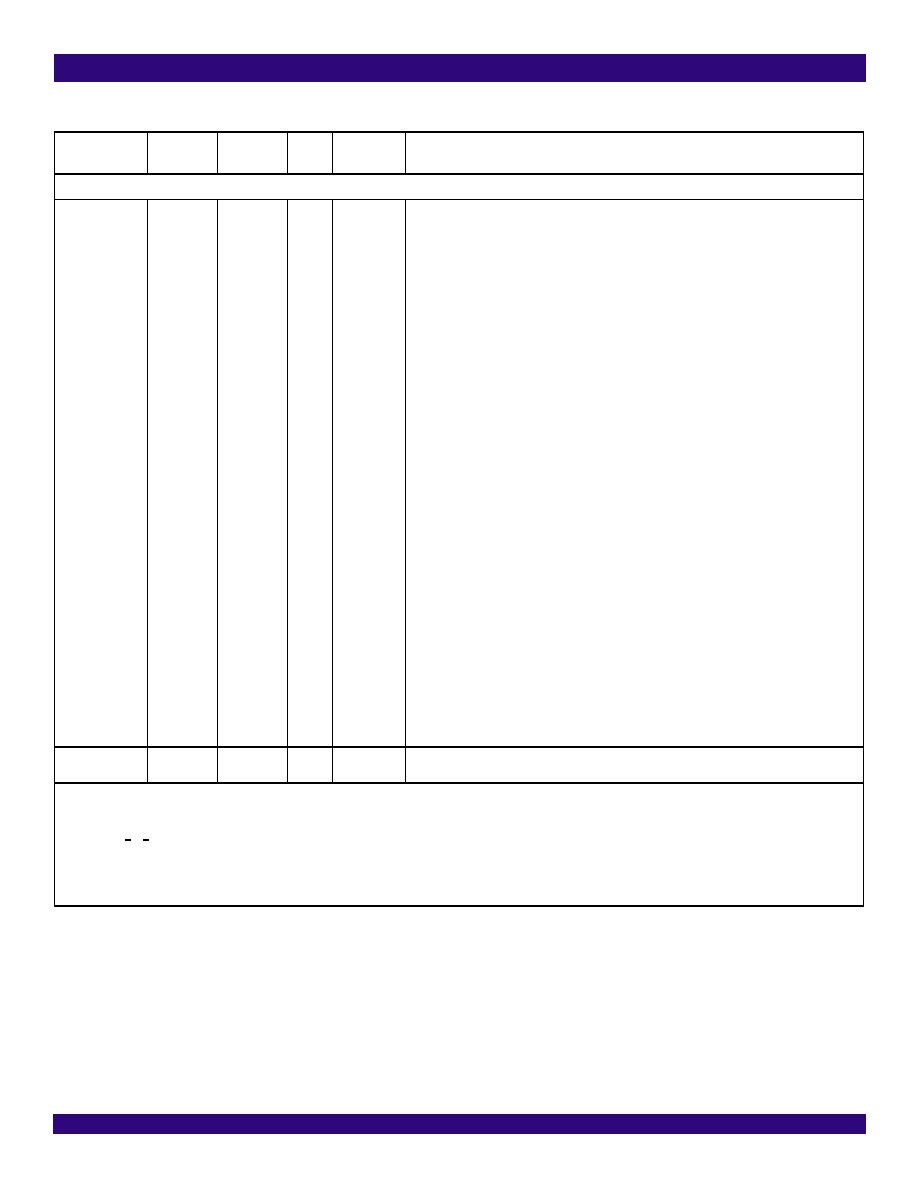
EBU WAN PLL
Pin Description
17
September 11, 2009
Others
IC1
IC2
IC3
IC4
IC5
IC6
IC7
IC8
IC9
IC10
IC11
IC12
IC13
IC14
IC15
IC16
IC17
2
17
24
25
26
27
36
37
44
46
58
63
64
65
66
67
19
2
16
23
24
25
26
34
35
42
43
55
59
60
61
62
63
18
--
IC: Internal Connected
Internal Use. These pins should be left open for normal operation.
NC
5, 28, 29, 45,
62
27
-
NC: Not Connected
Note:
1. All the unused input pins should be connected to ground; the output of all the unused output pins are don’t-care.
2. The contents in the brackets indicate the position of the register bit/bits.
3. N x 8 kHz: 1 < N < 19440.
4. N x E1: N = 1, 2, 3, 4, 6, 8, 12, 16, 24, 32, 48, 64.
5. N x T1: N = 1, 2, 3, 4, 6, 8, 12, 16, 24, 32, 48, 64, 96.
6. N x 13.0 MHz: N = 1, 2, 4.
7. N x 3.84 MHz: N = 1, 2, 4, 8, 16, 10, 20, 40.
Table 1: Pin Description (Continued)
Name
Pin No.
(NL68)
Pin No.
(TQFP 64)
I/O
Type
Description 1
发布紧急采购,3分钟左右您将得到回复。
相关PDF资料
IDT82V3255TFG
IC PLL WAN SMC STRATUM 3 64-TQFP
IDT82V3280APFG
IC PLL WAN SE STRATUM 2 100TQFP
IDT82V3285AEQG
IC PLL WAN SE STRATUM 100TQFP
IDT82V3285EQG
IC PLL WAN SE STRATUM 100TQFP
IDT82V3288BCG
IC PLL WAN 3E STRATUM 2 208CABGA
IDT82V3355EDG
IC PLL WAN SYNC ETHERNET 64TQFP
IDT82V3358EDG
IC PLL WAN SYNC ETHERNET 64TQFP
IDTCSPT857DNLG8
IC PLL CLK DVR SDRAM 40-VFQFPN
相关代理商/技术参数
IDT82V3202NLG8
功能描述:IC PLL WAN EBU SGL 68-VFQFPN RoHS:是 类别:集成电路 (IC) >> 时钟/计时 - 专用 系列:- 标准包装:1,500 系列:- 类型:时钟缓冲器/驱动器 PLL:是 主要目的:- 输入:- 输出:- 电路数:- 比率 - 输入:输出:- 差分 - 输入:输出:- 频率 - 最大:- 电源电压:3.3V 工作温度:0°C ~ 70°C 安装类型:表面贴装 封装/外壳:28-SSOP(0.209",5.30mm 宽) 供应商设备封装:28-SSOP 包装:带卷 (TR) 其它名称:93786AFT
IDT82V3202NLGBLANK
制造商:IDT 制造商全称:Integrated Device Technology 功能描述:EBU WAN PLL
IDT82V3255
制造商:IDT 制造商全称:Integrated Device Technology 功能描述:WAN PLL
IDT82V3255_08
制造商:IDT 制造商全称:Integrated Device Technology 功能描述:WAN PLL
IDT82V3255DK
制造商:IDT 制造商全称:Integrated Device Technology 功能描述:WAN PLL
IDT82V3255DKG
功能描述:IC PLL WAN SMC STRATUM 3 64-TQFP RoHS:是 类别:集成电路 (IC) >> 时钟/计时 - 专用 系列:- 标准包装:1,500 系列:- 类型:时钟缓冲器/驱动器 PLL:是 主要目的:- 输入:- 输出:- 电路数:- 比率 - 输入:输出:- 差分 - 输入:输出:- 频率 - 最大:- 电源电压:3.3V 工作温度:0°C ~ 70°C 安装类型:表面贴装 封装/外壳:28-SSOP(0.209",5.30mm 宽) 供应商设备封装:28-SSOP 包装:带卷 (TR) 其它名称:93786AFT
IDT82V3255DKG8
功能描述:IC PLL WAN SMC STRATUM 3 64-TQFP RoHS:是 类别:集成电路 (IC) >> 时钟/计时 - 专用 系列:- 标准包装:1,500 系列:- 类型:时钟缓冲器/驱动器 PLL:是 主要目的:- 输入:- 输出:- 电路数:- 比率 - 输入:输出:- 差分 - 输入:输出:- 频率 - 最大:- 电源电压:3.3V 工作温度:0°C ~ 70°C 安装类型:表面贴装 封装/外壳:28-SSOP(0.209",5.30mm 宽) 供应商设备封装:28-SSOP 包装:带卷 (TR) 其它名称:93786AFT
IDT82V3255EDGBLANK
制造商:IDT 制造商全称:Integrated Device Technology 功能描述:WAN PLL